

Back in school, there was an HP plotter well hidden in a closet in the science department. I got to play with it for a while and always wanted to have one of my own. Fast forward many, many years. Stepper motors are easily available, I am back into doing stuff with electronics and micro-controllers, and I recently saw someone creating displays with engraved acrylic. This triggered me to finally build my own plotter.
opensource.com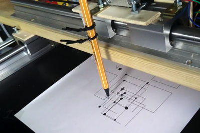
As an old-school 5V guy, I really like the original Arduino Uno. Here's a list of the other components I used (fyi, I am not affiliated with any of these companies):
- FabScan shield: Physically hosts the stepper motor drivers.
- SilentStepSticks: Motor drivers, as the Arduino on its own can't handle the voltage and current that a stepper motor needs. I am using ones with a Trinamic TMC2130 chip, but in standalone mode for now. Those are replacements for the Pololu 4988, but allow for much quieter operation.
- SilentStepStick protectors: Diodes that prevent the turning motor from frying your motor drivers (you want them, believe me).
- Stepper motors: I selected NEMA 17 motors with 12V (e.g., models from Watterott and SparkFun).
- Linear guide rails
- Wooden base plate
- Wood screws
- GT2 belt
- GT2 timing pulley
This is a work in progress that I created as a personal project. If you are looking for a ready-made kit, then check out the MaXYposi from German Make magazine.
Hardware setup
As you can see here, I started out much too large. This plotter can't comfortably sit on my desk, but it's okay, as I did it for learning purposes (and, as I have to re-do some things, next time I'll use smaller beams).
opensource.com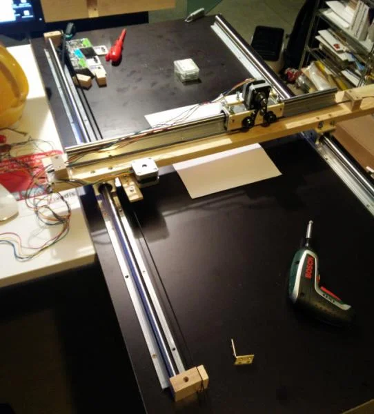
The belt is mounted on both sides of the rail and then slung around the motor with some helper wheels:
opensource.com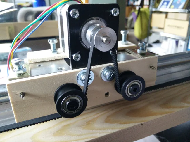
I've stacked several components on top of the Arduino. The Arduino is on the bottom, above that is the FabScan shield, next is a StepStick protector on motor slots 1+2, and the SilentStepStick is on top. Note that the SCK and SDI pins are not connected.
opensource.com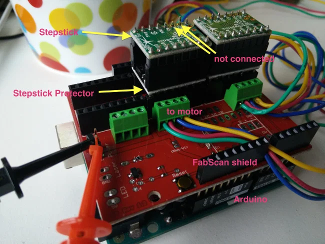
Be careful to correctly attach the wires to the motor. When in doubt, look at the data sheet or an ohmmeter to figure out which wires belong together.
Software setup
While software like grbl can interpret so-called G-codes for tool movement and other things, and I could have just flashed it to the Arduino, I am curious and wanted to better understand things. (My X-Y plotter software is available at GitHub and comes without any warranty.)
The basics
To drive a stepper motor with the StepStick (or compatible) driver, you basically need to send a high and then a low signal to the respective pin. Or in Arduino terms:
digitalWrite(stepPin, HIGH);
delayMicroseconds(30);
digitalWrite(stepPin, LOW);
Where stepPin is the pin number for the stepper: 3 for motor 1 and 6 for motor 2.
Before the stepper does any work, it must be enabled.
digitalWrite(enPin, LOW);Actually, the StepStick knows three states for the pin:
- Low: Motor is enabled
- High: Motor is disabled
- Pin not connected: Motor is enabled but goes into an energy-saving mode after a while
When a motor is enabled, its coils are powered and it keeps its position. It is almost impossible to manually turn its axis. This is good for precision purposes, but it also means that both motors and driver chips are "flooded" with power and will warm up.
And last, but not least, we need a way to determine the plotter's direction:
digitalWrite(dirPin, direction);The following table lists the functions and the pins
| Function | Motor1 | Motor2 |
|---|---|---|
| Enable | 2 | 5 |
| Direction | 4 | 7 |
| Step | 3 | 6 |
Before we can use the pins, we need to set them to OUTPUT mode in the setup() section of the code
pinMode(enPin1, OUTPUT);
pinMode(stepPin1, OUTPUT);
pinMode(dirPin1, OUTPUT);
digitalWrite(enPin1, LOW);
With this knowledge, we can easily get the stepper to move around:
    totalRounds = ...
    for (int rounds =0 ; rounds < 2*totalRounds; rounds++) {
       if (dir==0){ // set direction
         digitalWrite(dirPin2, LOW);
       } else {
         digitalWrite(dirPin2, HIGH);
       }
       delay(1); // give motors some breathing time
       dir = 1-dir; // reverse direction
       for (int i=0; i < 6400; i++) {
         int t = abs(3200-i) / 200;
         digitalWrite(stepPin2, HIGH);
         delayMicroseconds(70 + t);
         digitalWrite(stepPin2, LOW);
         delayMicroseconds(70 + t);
       }
    }
This will make the slider move left and right. This code deals with one stepper, but for an X-Y plotter, we have two axes to consider.
Command interpreter
I started to implement a simple command interpreter to use path specifications, such as:
"X30|Y30|X-30 Y-30|X-20|Y-20|X20|Y20|X-40|Y-25|X40 Y25to describe relative movements in millimeters (1mm equals 80 steps).
The plotter software implements a continuous mode, which allows a PC to feed large paths (in chunks) to the plotter. (This how I plotted the Hilbert curve in this video.)
Building a better pen holder
In the first image above, the pen was tied to the Y-axis with some metal string. This was not precise and also did not enable the software to raise and lower the hand (this explains the big black dots).
I have since created a better, more precise pen holder that uses a servo to raise and lower the pen. This new, improved holder can be seen in this picture and in the Hilbert curve video linked above.
opensource.com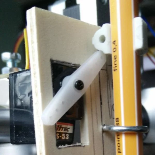
The pen is attached with a little clamp (the one shown is a size 8 clamp typically used to attach cables to walls). The servo arm can raise the pen; when the arm goes down, gravity will lower the pen.
Driving the servo
Driving the servo is relatively straightforward: Just provide the position and the servo does all the work.
#include <Servo.h>

// Servo pin
#define servoData PIN_A1

// Positions
#define PEN_UP 10
#define PEN_DOWN 50

Servo penServo;

void setup() {
  // Attach to servo and raise pen
  penServo.attach(servoData);
  penServo.write(PEN_UP);
}
I am using the servo headers on the Motor 4 place of the FabScan shield, so I've used analog pin 1.
Lowering the pen is as easy as:
penServo.write(PEN_DOWN);Next steps
One of my next steps will be to add some end detectors, but I may skip them and use the StallGuard mode of the TMC2130 instead. Those detectors can also be used to implement a home command.
And perhaps in the future I'll add a real Z-axis that can hold an engraver to do wood milling, or PCB drilling, or acrylic engraving, or ... (a laser comes to mind as well).
This was originally published on the Some Things to Remember blog and is reprinted with permission.


1 Comment