

I love Christmas decorations and lights, and I'd been wanting to do an programmable LED project for a long time. Recently, I built a light array made of LED lights, ping pong balls, and a Raspberry Pi Zero. I thought it was worth sharing, because it ended up being relatively easy but also educational.
It's mostly my own design, with some inspiration from YouTube videos. You can find the source code and build instructions in my Git repository.
Shopping list
- Raspberry Pi Zero
- Pibow Case
- 5v 2A USB power supply
- Poster frame
- 255 ping pong balls
- Hot glue gun and LOTS of hot glue sticks
- Soldering iron
- Solder
- 22 AWG 0.35mm solid core wiring
- 10 meters of WS2812(B) LED strip lights (30 pixels per meter)
- Multimeter
- Wire cutters
- Wire strippers
Design the Raspberry Pi light display
My design was driven by the size of the poster frame I happened to have available. I got 30 pixel per meter tape from Ali Express, which cut nicely into 0.5m sections, so that gave me 15 LEDs across. Ping pong balls are 40mm, so I measured and placed the lines 40mm apart, with the LED Strip in the middle of each 40mm section. This gave me 17 lines down in total. My array was therefore 15×17. If you try this yourself, yours can be a different size.
To get power to the array and the Raspberry Pi, I placed the open connections for both data and power at the bottom of the board. I didn't have that many LEDs needing power, so I was able to use the 5v out GPIO from the Raspberry Pi Zero to power them. I run them at 50% brightness, which is easily bright enough to see in the day and at night through my window.
Wiring
In my design, I started at the bottom of the board and wired up in an S-curve. This made soldering easier because loops at the end of each row didn't have to return all the way back to the start of each line. The WS2812 data lines do require you to wire the data the correct way: power can be fed from either side of the strip, but data must be fed from the side with the arrows pointing away.
My wiring looks like this (this is abbreviated for clarity, in real life it's 17 lines deep):
<---------------\
                |
/---------------/
|
\---------------< # Pi connected here
Build the display with your Raspberry Pi
Once the design and wiring plan was sorted, it was time to get started on the build.
I measured and drew my lines in pencil on the poster backboard. The WS2812 strips I got came with sticky tape on the back, so I just removed the backing and attached that directly to the backboard. I was sure to position each strip so that the data arrows went one way, then back the other, to ensure that the lights could be daisy-chained correctly for the Pi's instructions.
Once all light strips were attached, I cut three similar lengths of wire and connected the 5v, data, and ground lines from the end of each light section to the one above it.
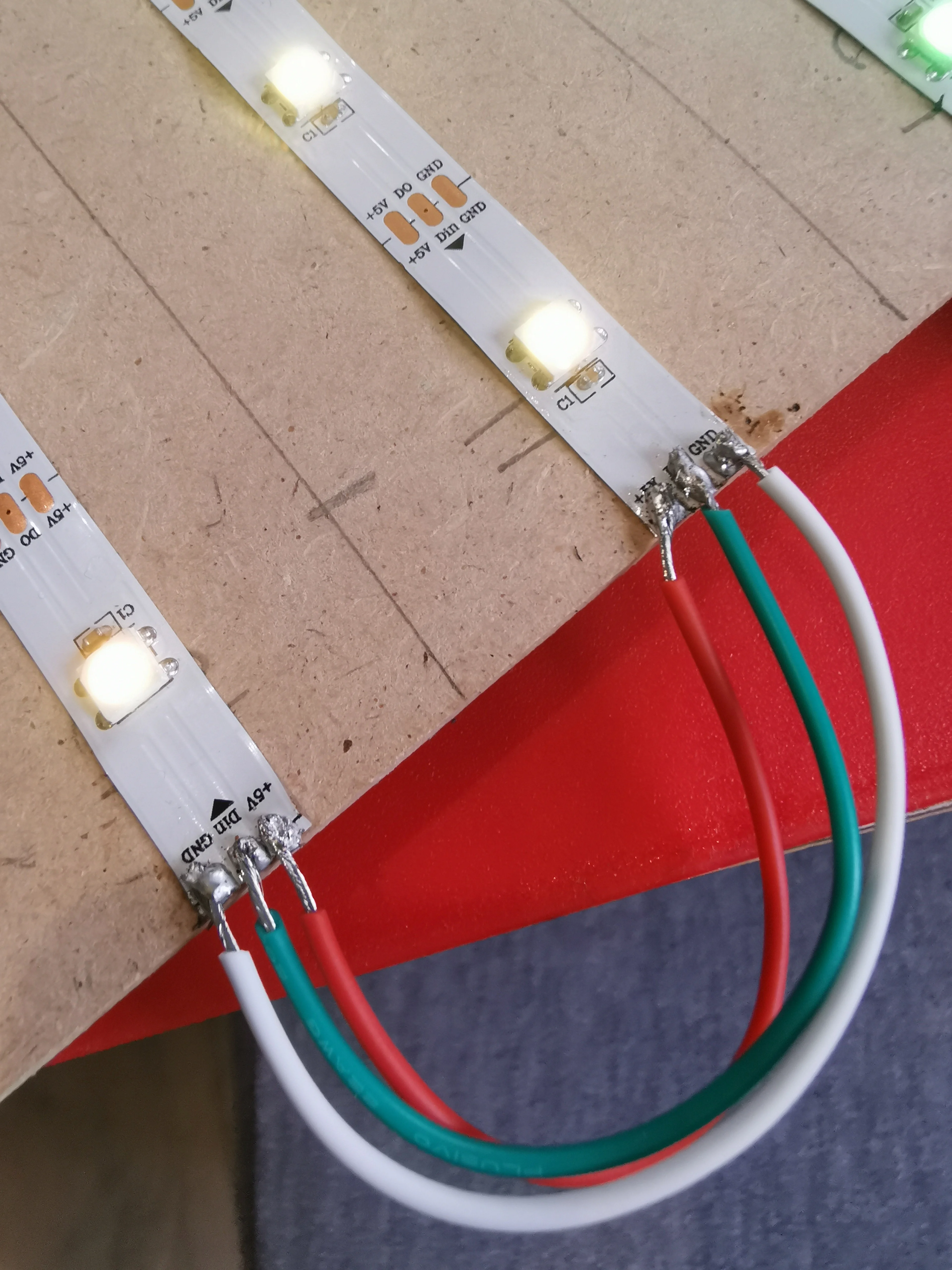
(Brian McCafferty, CC BY-SA 4.0)
After completing each row, I checked continuity between the 5v and ground lines between each strip to ensure my joins were correct. I also checked that I had not accidentally bridged any connections, so I verified that there was no continuity between the 5v and ground lines (in other words, a 5v wire on one line didn't bridge to the ground on the next line.) I also ran some tests to ensure everything was lighting up correctly (see the code section for my strand tests.)
Once this was complete, I started to cut holes in the ping pong balls by stabbing scissors into the bottom of them, and cutting a small hole for the LED to shine into. There was no exact science to this, and each one was different, but the effect really worked. I was working with 30 pixels per meter, so my lighting had about 30mm between each LED. A ping pong ball is 40mm across, but I wasn't about to start soldering each LED individually! First of all, I'm not that good at soldering (as my photos show), and anyway, I thought "Well, they're ping pong balls. I can just squash them together!"
And that's what I did.
I placed a hot glue blob around each LED and then placed a ping pong ball onto the LED, held it for about five seconds, and moved on to the next one. I held onto the previous ping pong ball as I slid the next one in, pushing it against the first before "folding" it into its neighbor. The effect worked really well. I was happy with what it was looking like straight away. It also had the nice bonus of hiding my bad soldering job ;)
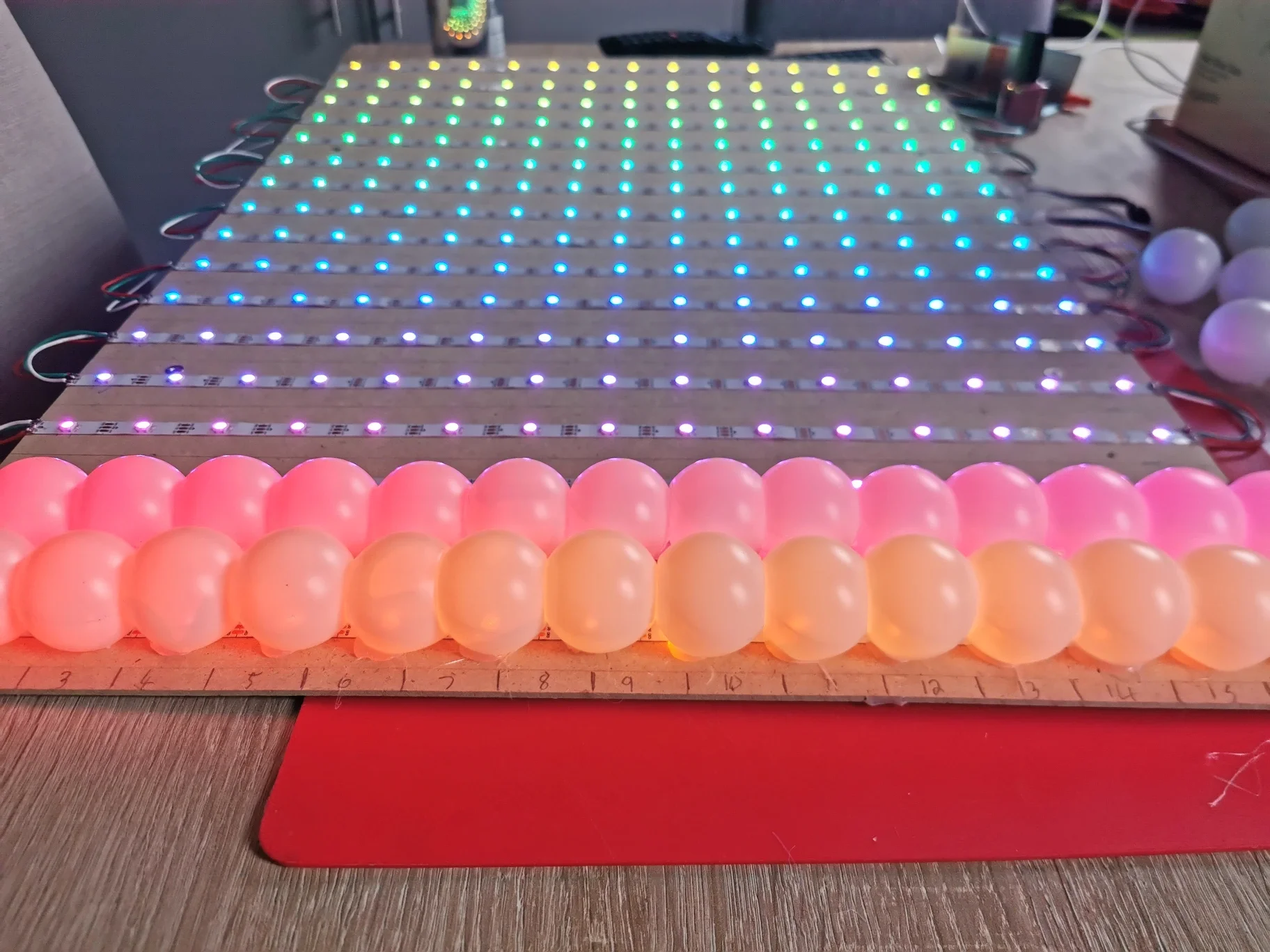
(Brian McCafferty, CC BY-SA 4.0)
I continued doing this for 255 LEDs and ping pong balls. There were a few crushed ping pong balls in the process, but in the end, I got there.
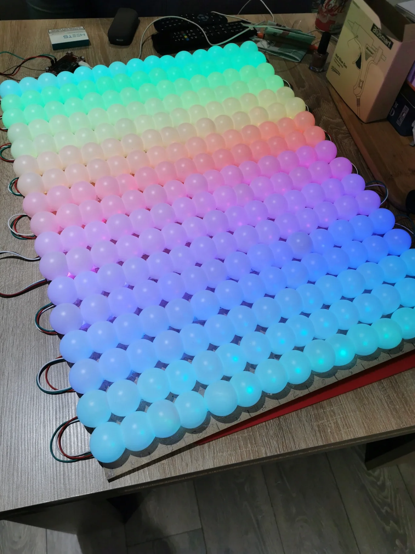
(Brian McCafferty, CC BY-SA 4.0)
Test the code
For the test code to ensure that everything was working, I used this Adafruit guide which lights each LED in red, green, and blue, and then does a rainbow cycle. I used this when I was building to ensure my connections were correct and that everything was soldered correctly.
After that, I designed a grid in a spreadsheet to map each pixel to a grid position. This helped to make building the images easier. Since my pixel numbers run in a zig-zag pattern, it would have been hard to keep track of each LED (e.g. LED A1 was 256 and B1 was 226).
Once this was all set, it was time to design some images on paper and in the spreadsheet. Then it was time to code! It got a bit addictive and I started adding some animation (using loops and turning pixels onto one color and then another color).
The end result was everything I'd hoped it would be.
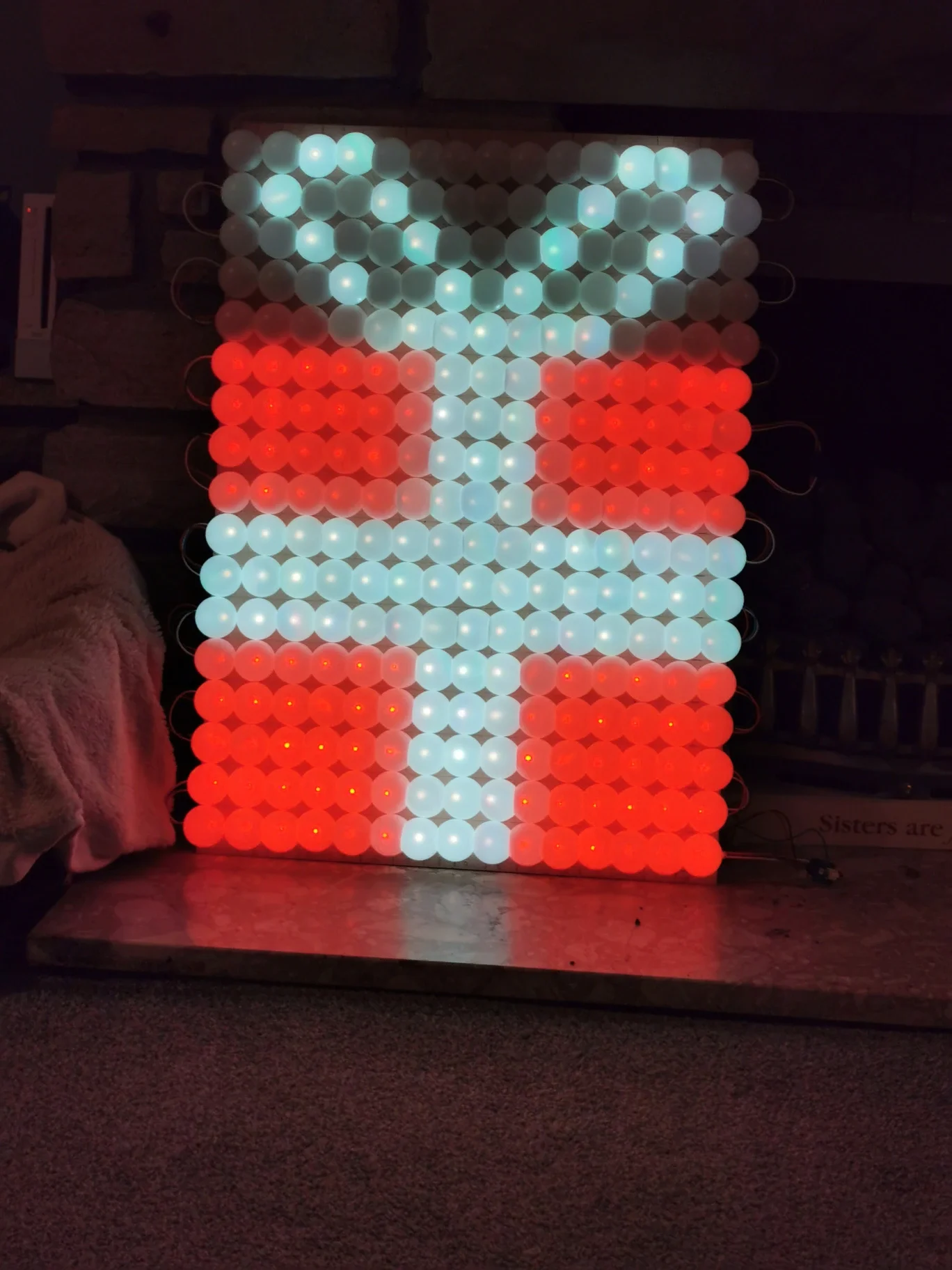
(Brian McCafferty, CC BY-SA 4.0)
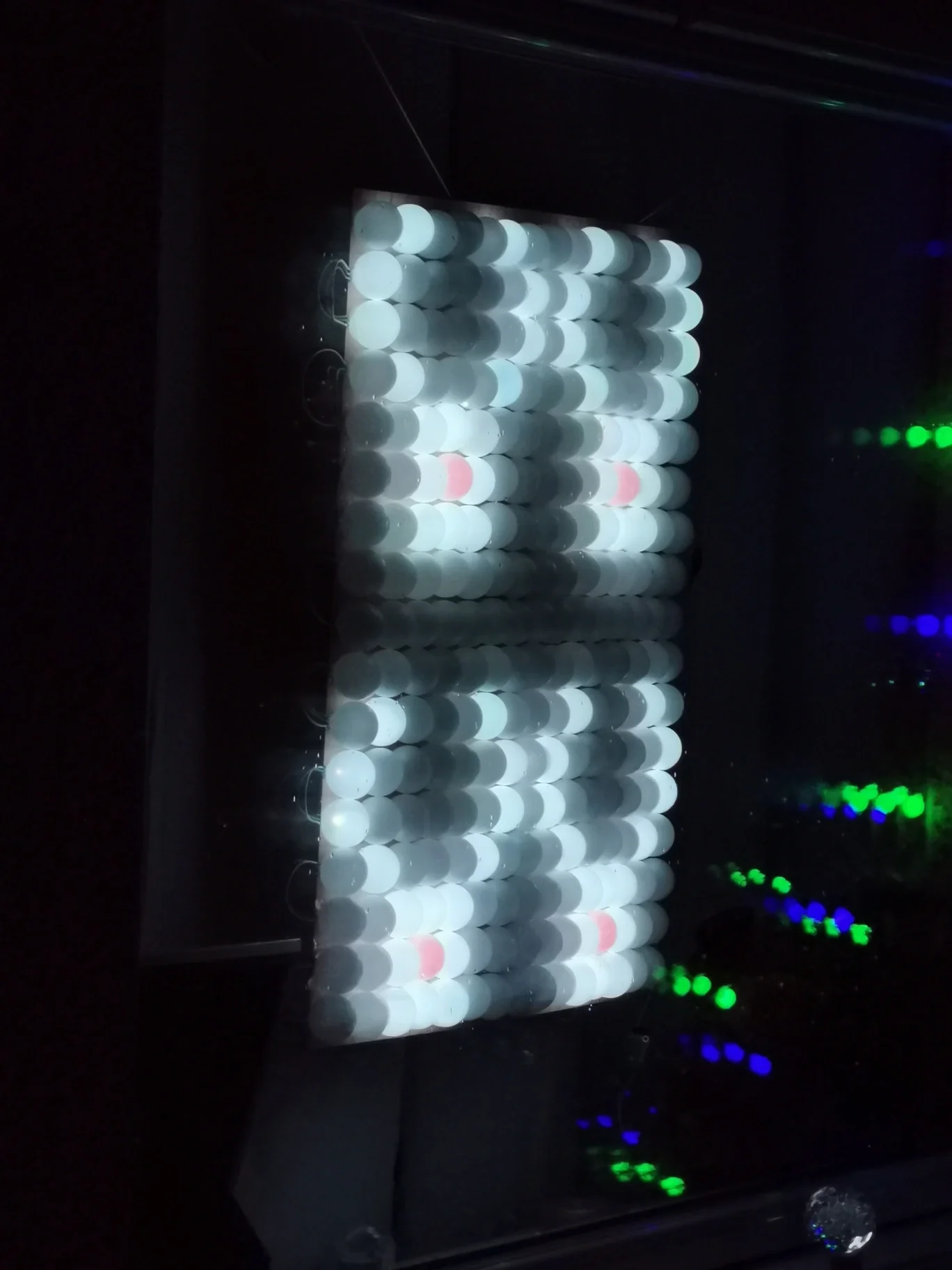
(Brian McCafferty, CC BY-SA 4.0)
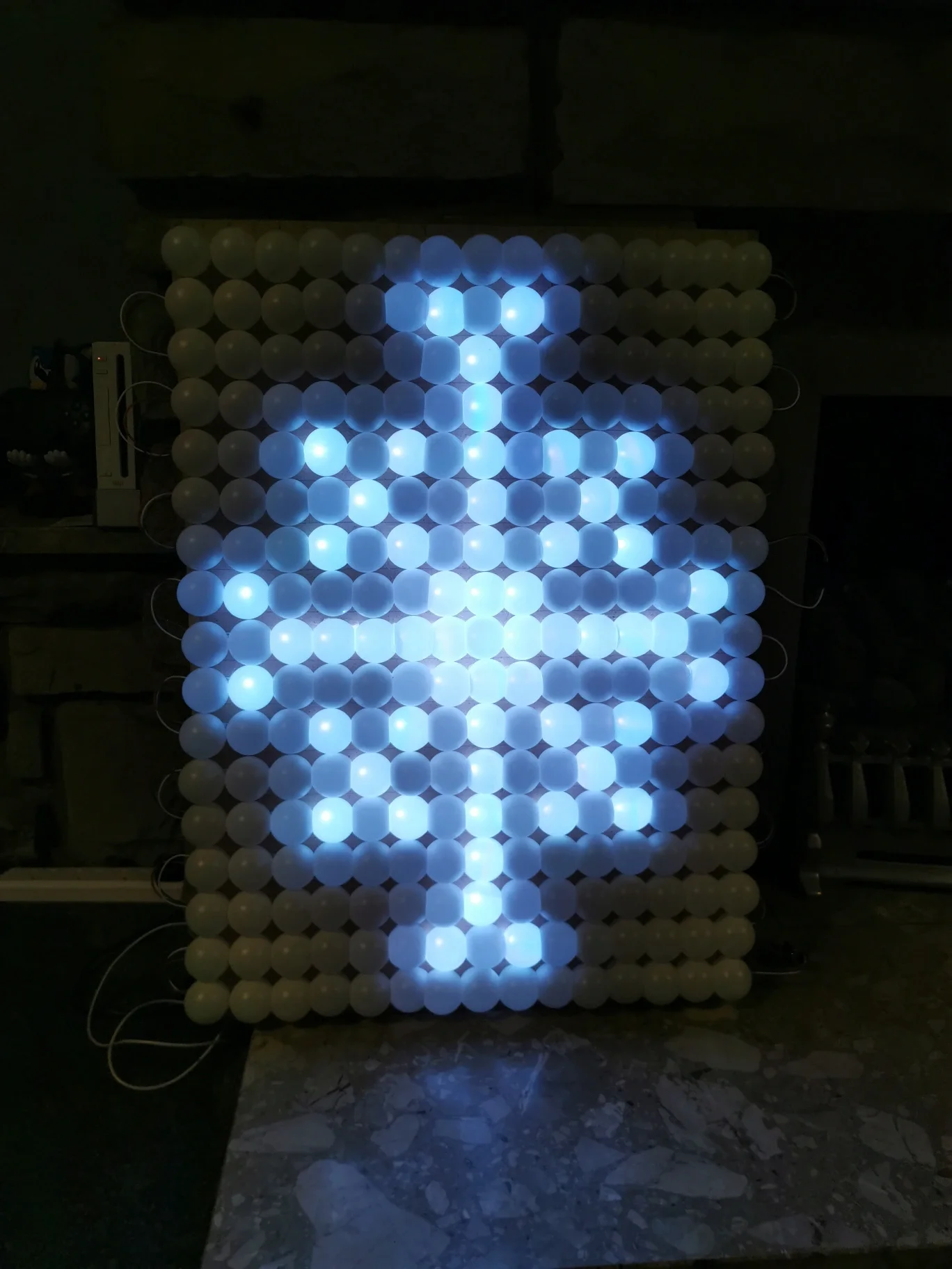
(Brian McCafferty, CC BY-SA 4.0)
A Raspberry Pi light display all year
I am not sure this will ever be truly finished. Nearly every night since it's been up in the window, I've added some new images and animations. I'm already thinking about what to do for New Year's Eve. I also won't be putting this back in storage with my Christmas decorations in January. I just need to think of other things to draw on it to make it a year-round project! A friend of mine suggested a pixel Mario and I love that idea!
My code also needs a little work. For example, I do some scrolling text, but I redraw the whole board for each position of the text, so it took quite a bit of time to do. I think I can do something with loops, or perhaps the image library can help scroll the letters easier, and make it easier to add text rather than turning each pixel on and off at every step.
I've got a photo record of my progress from start to finish: LED Ping Pong Wall.
You can also see a video of it in action here: XMas light display.
I'm really pleased with how this turned out, and I think it looks amazing. I'm very excited to try some other LED projects in the future. I encourage you to try a light array of your own even as your first project. It's easier than it looks!


1 Comment