My team from Singapore Polytechnic made a water collection vessel for the module Engineering & Design, as part of the Engineering Academy program. The team consisted of four members from different disciplines: Thomas and Ryan from the Diploma in Mechanical Engineering, and Hwee Peng and myself, Ajay, from the Diploma in Electrical and Electronic Engineering. The project took several months to complete, from December 2015 to February 2016.
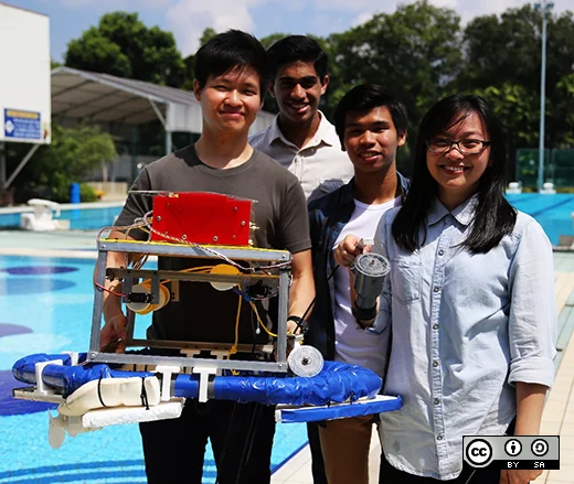
The Engineering Academy program is offered to top students from the School of Electrical and Electronic Engineering, as well as the School of Mechanical and Aeronautical Engineering in Singapore Polytechnic. The program aims to impart skills from a multitude of disciplines: electrical, electronics, mechanics, chemistry, design, and business.
The project statement we were presented with at the beginning of the semester was: "Design a vehicle that can take two samples of water, at one meter and two meters underwater." This posed a challenge to us as there were many intricacies of the vehicle that we had to think about, and it was a huge undertaking.
However, we welcomed the challenge with open arms. We knew it would put all of our knowledge to the test and would necessitate the search for even more information on our own. This article will outline the very iterative process of planning and prototyping, and showcase the fruit of our labor.
Planning I
We came up with many ideas after exercising our foresight by listing as many challenges we were likely to face, and then coming up with their corresponding solutions. After all, it was going to be a vehicle which would either be floating or submerging into the water. Once water comes into the picture whenever any electronics are concerned, waterproofing is imperative. In hindsight, it is amusing that we even considered the idea of a submersible vehicle instead of just a simple floating vessel, given the amount of constraints we had in terms of time, materials, and fabrication methods.
Main body
For the main body of the vessel, we decided to employ the use of polyvinyl chloride (PVC) pipes for the base of the vessel, and acrylic to form the main supporting structure. We found that PVC was a relatively cheap yet buoyant material, and in a closed-pipe network will trap air within it, which helps with buoyancy even more. We wanted to use acrylic pieces as they were easy to fabricate and provided adequate structural support. All we needed was a 2D schematic drawing, and the laser cutter could do the rest of the work.
Container
Initially, we planned to use 12V solenoid valves to regulate water entry into the containers. However, we found that the valves provided to us by our lecturers did not work as intended for a peculiar reason. All components seemed to be working fine, however, the valves did not allow water to flow freely despite us carrying out extensive testing. We suspected that it had something to do with the strength of the solenoid within them, or perhaps it was due to a major design flaw right from the get-go.
As buying new valves were out of our budget and would have introduced a multitude of other problems, we hit the drawing boards again and did more research on water samplers.
We discovered the Van Dorn Water Sampler, which is an ingenious method of water collection, working upon elasticity and a quick-release mechanism. We simplified the design further to retrofit it into our vessel.
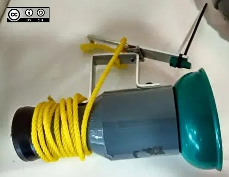
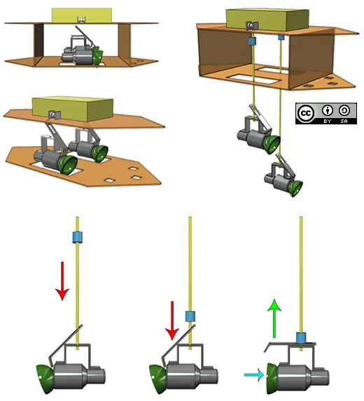
The graphic below depicts how the container is operated. It is lowered down by a nylon rope and upon reaching the desired depth, a messenger (a weight) is sent falling along the rope to strike the lever which would be released from its wedged position and cause the container to clamp shut, trapping water within it.
Lowering mechanism
We settled on the idea of lowering containers into the water to the respective depths, and collecting the water samples while the main body of the vessel remained floating. We first thought of using an arm to lower the container down and then bring it back up. However, this would have been possible only if we used the solenoid valve as part of the water container.
Since the solenoid valve idea had to be shelved, we had to come up with a new way of lowering the containers. We decided on using a rope and a motor to lower and raise the water containers, as this was the simplest design to complement the water container's design.
Fabrication I
Upon coming up with a satisfactory design, we proceeded to build the main body of the vessel using laser-cut acrylic pieces together with PVC pipes.
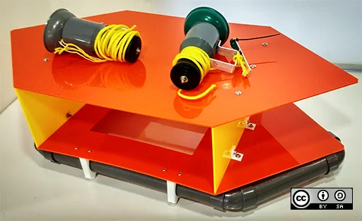
However, we found that the acrylic pieces were too weak to sustain the weight of the containers together with their messengers. The acrylic, being only 3mm (0.12") thick, meant that it was too fragile for our design. The resolution of forces would have resulted in them cracking or breaking quickly.
Our initial prototype was very short-lived as the entire acrylic frame had to be cast aside. We also discovered a complication with the mechanism actuating the water containers, the messenger. Alas, time to get back into planning once again!
Planning II
Our overall design made sense both physically as well as mathematically, however we had to come up with a brand new frame for the vessel, as well as come up with a new way of closing the water container. We got the bulk of the design correct, but still had to make a few major improvements.
Main body
We needed a newer, stronger frame. Given the limited resources and time, we decided to fabricate an aluminium frame by making use of aluminium L-brackets. It took quite a bit of time to perfect as we had to make sure our sawing and milling were precise, drilling was done properly, holes were aligned, and that our communication was effective.
Container actuating mechanism
Using a messenger to release the water container's lever proved to be quite the conundrum. It was not very easy to implement and would have resulted in a rather clunky user experience. Thus, we had to think of a new way of doing this. We racked our brains for possible solutions, and one of the ideas we stumbled upon was to use bicycle brakes to yank the lever up and shut the container. It was wonderfully simple to control via a servo motor!
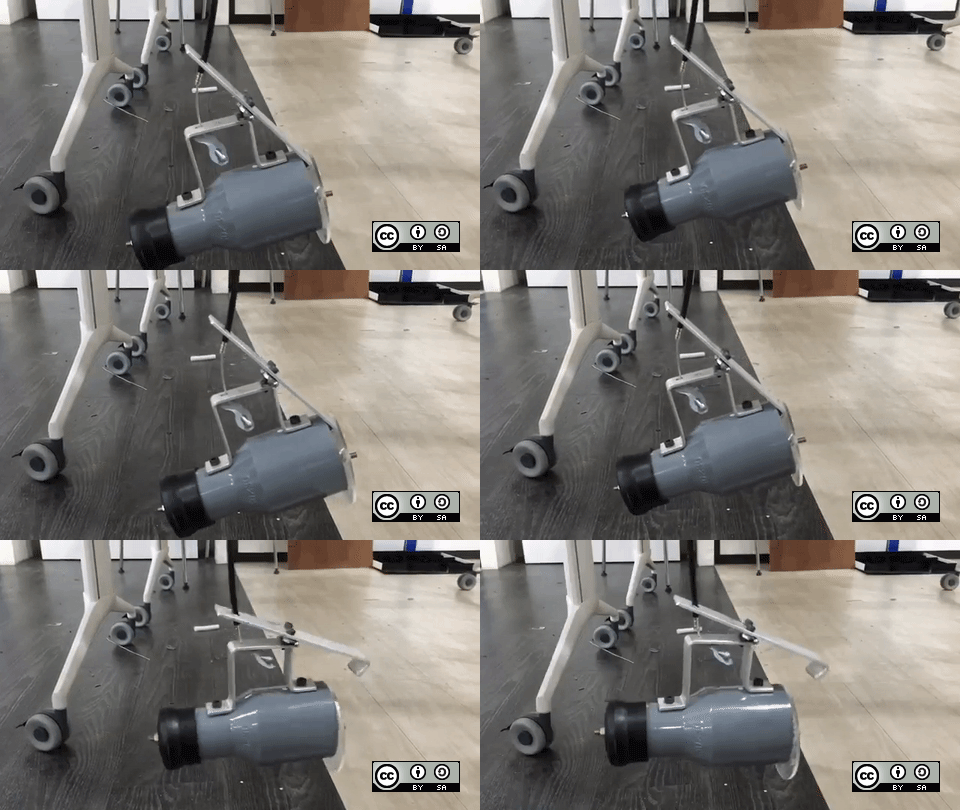
The above animation shows a working example of how our containers were actuated, being controlled by servo motors.
Fabrication II
Once we had a solid proof of concept, we had to join the pieces of the puzzle in the most elegant manner possible. You might be wondering, this article has covered lots about the mechanical aspect of Imp Bot (the name we ever so proudly bestowed upon our would-be work of art) but nothing about the electronics!
Imp Bot was controlled using a mobile application made using the MIT App Inventor, and communication was achieved via a Bluetooth module hooked up to an Arduino Mega board. It even had a GPS sensor on board to log sampling locations in the mobile application. The power was provided by a lithium-ion polymer battery, which was able to supply high current to two DC motors responsible for moving the 5kg (11 pounds) vessel around.
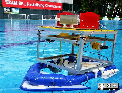
And lo and behold, Imp Bot basking in its true glory! Testing went smoothly and we achieved our aim of collecting water from one meter and two meters underwater.
Conclusion
To conclude, I hope that this article has shown the amount of work that has to be put into a project of this calibre. The project statement seemed very simple on the surface, but once we delved into the specifics of the vessel, we discovered many small but significant hurdles we had to cross.
The journey was arduous. We spent many late nights designing Imp Bot and crunching the numbers behind it. We also spent many long days in the workshop fabricating and testing it. One thing, however, is for certain: we made sure we had fun, and that we learned something at the end of the day.
I personally thoroughly enjoyed myself despite the incredible amount of work we had to put in. In the end, I am glad to say it all paid off. This video provides a quick overview of the project, and the team.
For more information, do visit our blog. We documented our entire journey over there if you would like to explore it in greater depth. All Arduino code can be found here. All schematic diagrams and .stl files can be found in this Google Drive folder, licensed under the Creative Commons Attribution 4.0 International license. The .stl files may be opened with any 3D model viewing software such as MakerWare or Cura. The raw schematic files (.iam and .ipt) were created with Autodesk Inventor, and can be opened in Autodesk Inventor 2014 or any newer version of the software.



Comments are closed.