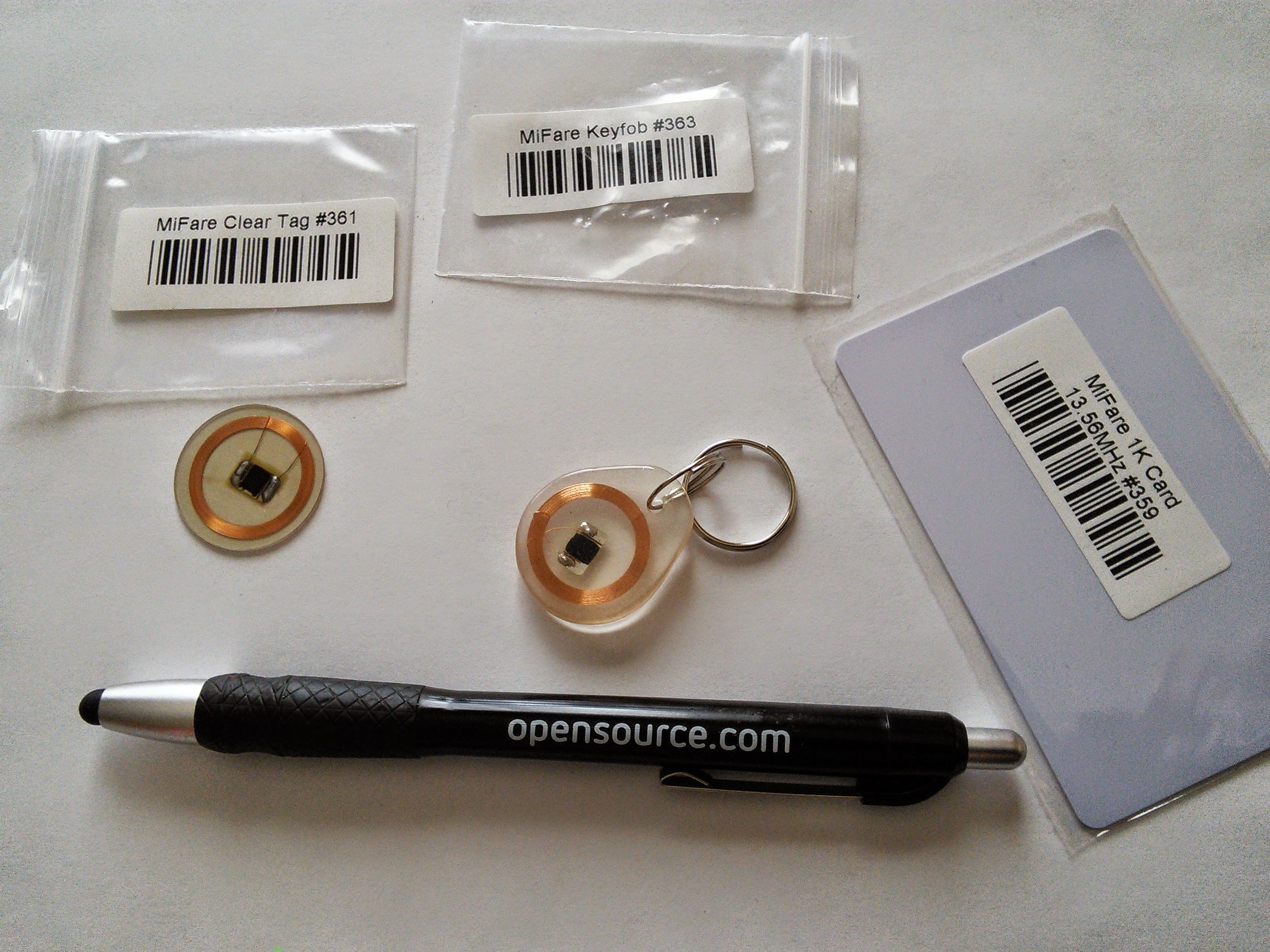
RFIDs—we use them every day. With every visit to the supermarket, public library, bookstore, or department store, we handle objects that have an RFID tag, which stands for Radio Frequency Identification. For one, these small tags make it easier for shop owners to keep inventory by tracking the flow of items as they're brought in, moved around, and purchased. RFID tags are usually composed of a small electronic chip that can store a few thousand bytes and an antenna that commonly takes the shape of a tight spiral—sometimes squared, sometimes circular.
This article is about how I tinkered with the Adafruit PN532 controller shield to read and write RFID tags.
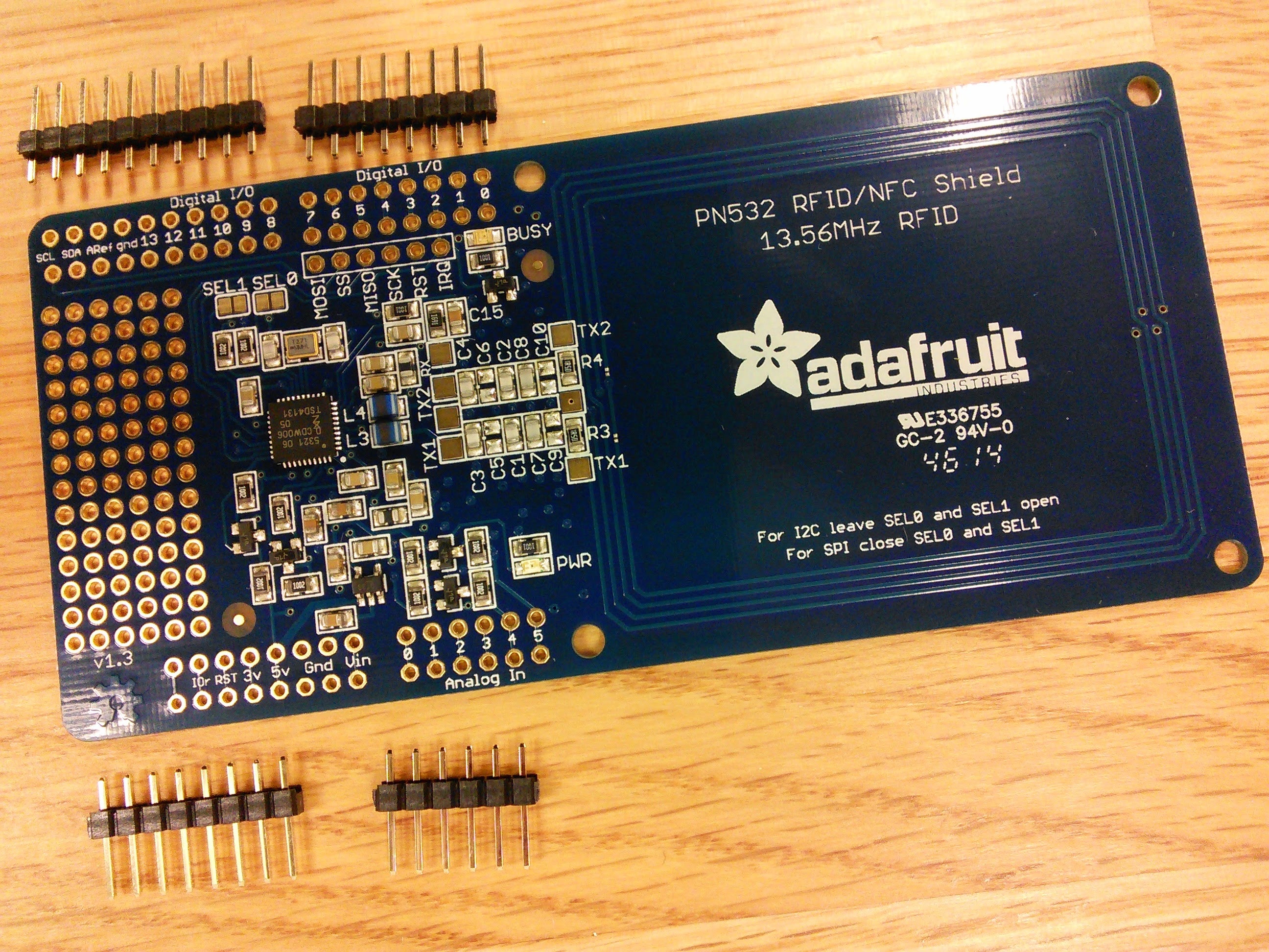
To read and write information onto an RFID tag, you need a device composed of an antenna, radio circuitry, and a few digital electronic components. That's exactly what the Adafruit PN532 controller shield is. It attaches to an Arduino board that provides the programming logic for reading or writing data.
History: RFID readers have a colorful history that dates back to the Cold War, when inventor Leon Theremin conceived a passive listening device known as "The Thing" that allowed Soviet intelligence to listen to conversations in the U.S. Ambassador's office in Moscow from 1945-1952.
The hardware
To start our exploration of the RFD/NFC shield, we need the following items:
- PN532 NFC/RFID controller shield for Arduino + extras
- Assorted RFID tags
- Arduino Uno R3 board
- 9 VDC power adapter
- Standard A-B USB Cable
Adafruit provides a nice starting guide for assembly and testing of the shield. I started by soldering connectors into the shield:
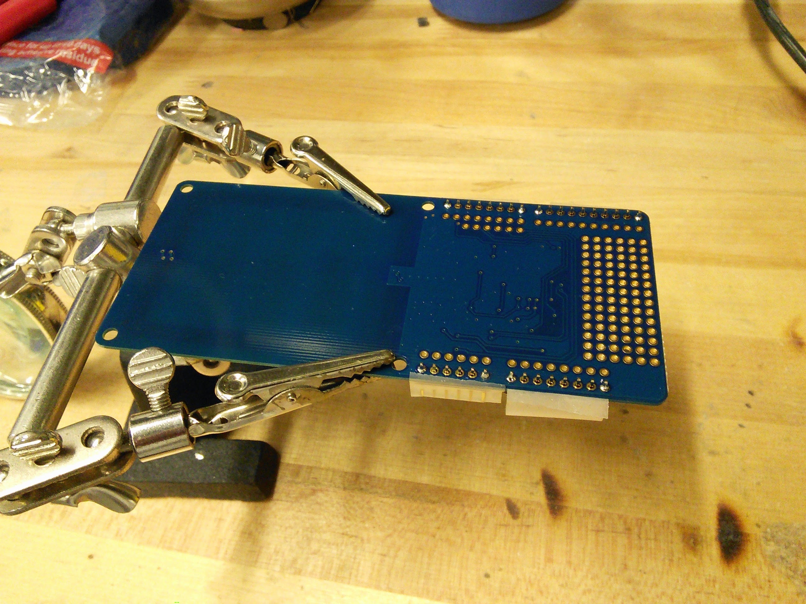
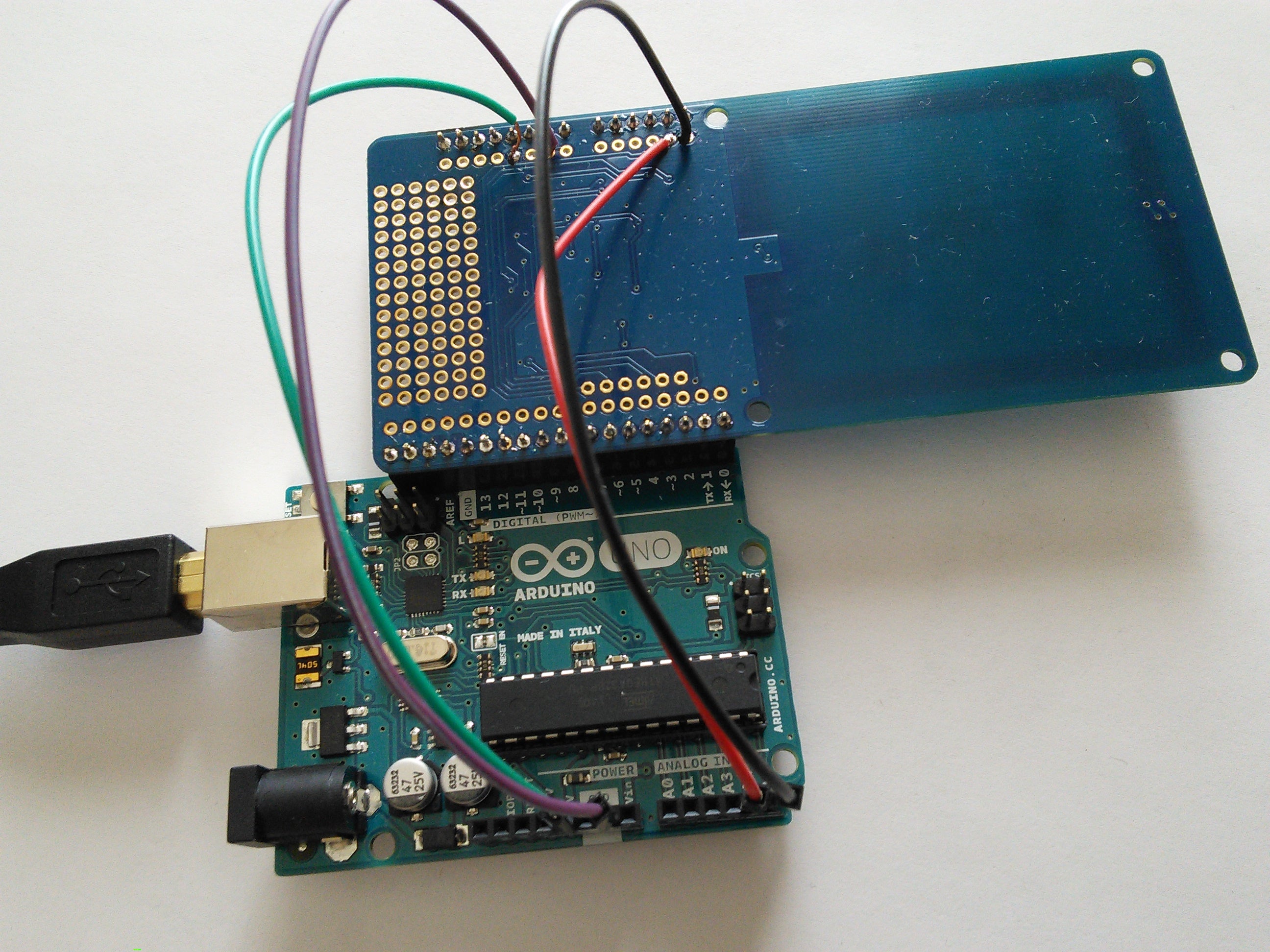
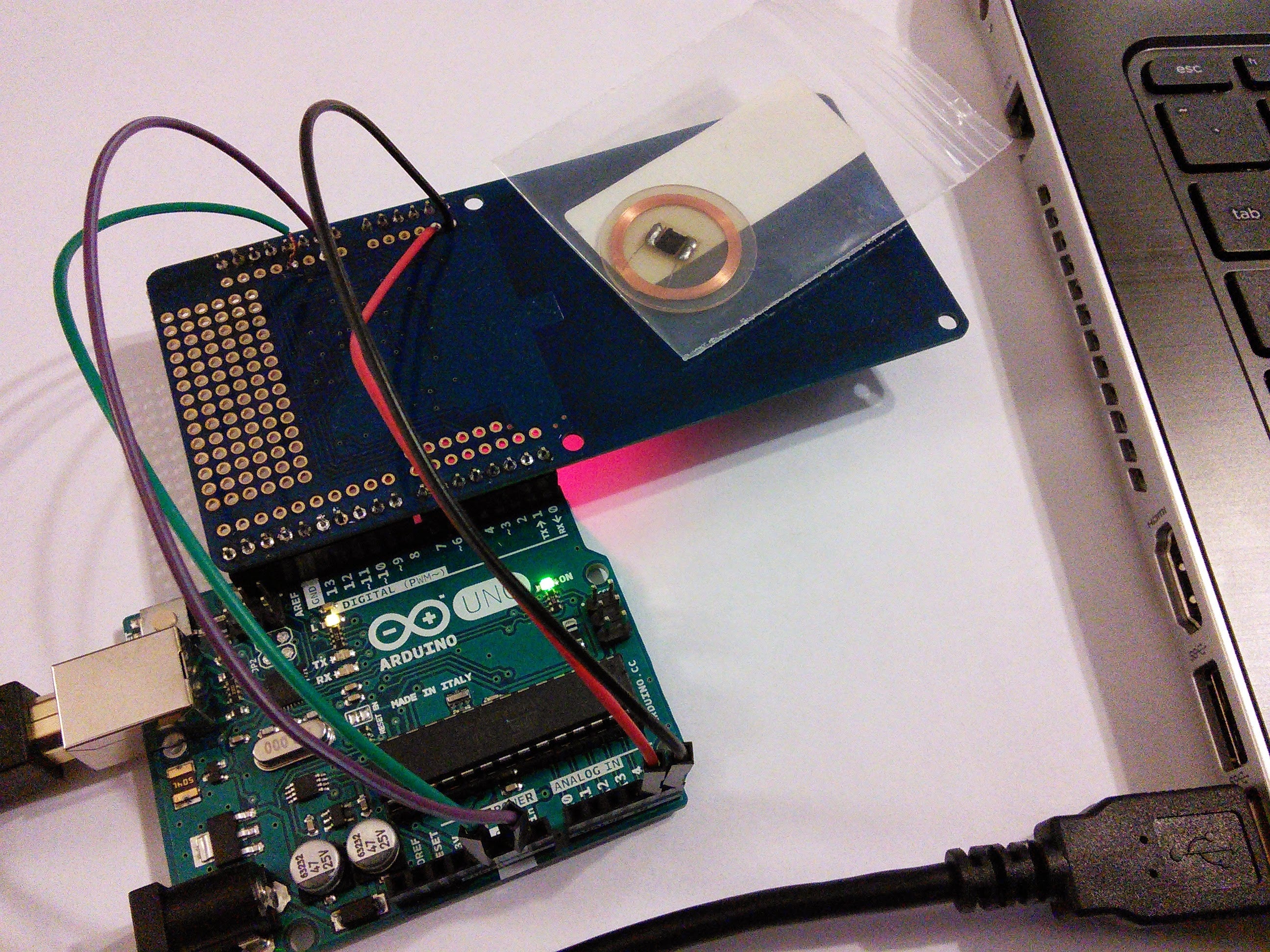
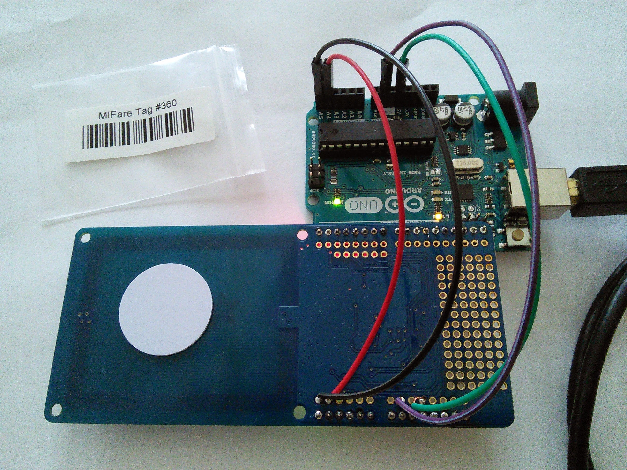
Only then did I realize that these connectors should be soldered on the other side of the shield. Undeterred by the error, I used one side of the connectors and soldered jumping cables to wire the other side. As usual, this mishap was a learning opportunity—I realized that the shield only really needed five wires and that most of the connectors are really for mechanical support. The essential wires are:
- Two wires for the Analog 4 and 5 connectors, support the I2C communications protocol
- The digital line 2 of the Arduino is connected to an interruption line from the shield to notify the Arduino when an RFID tag is within reading range of the shield's antenna
- Two more wires bring power (5V and GND)
The software
Having (clumsily but surely) taken care of the wiring, I moved on to the software stage.
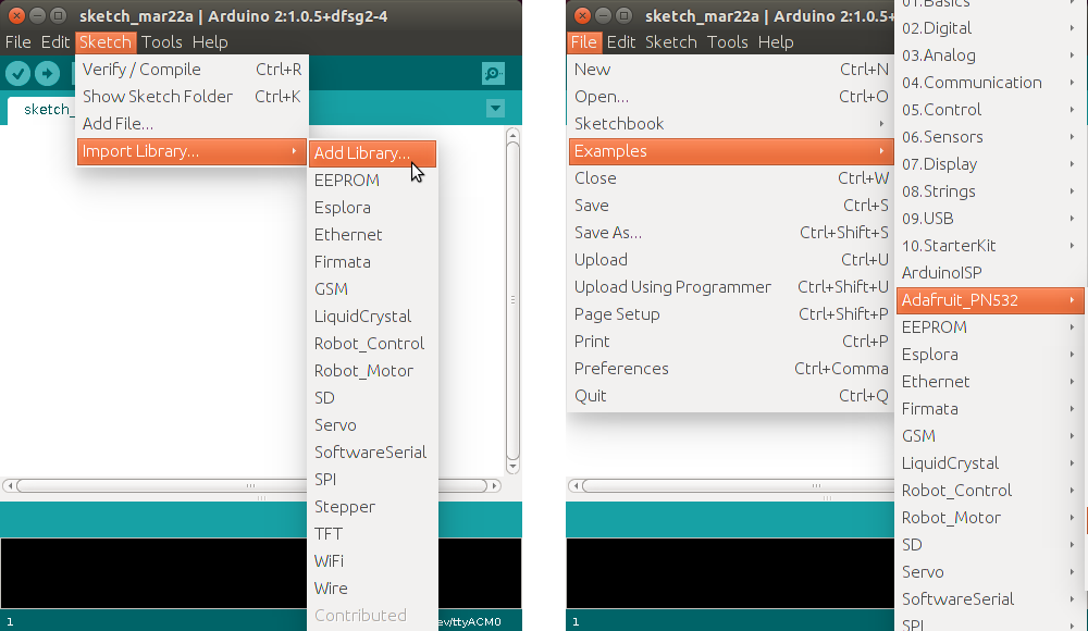
Following the quick start guide instructions, I cloned the GitHub repository of the Adafruit-PN532 library. I then renamed the directory as "Adafruit_PN532" (the library import feature of the Arduino IDE does not accept "-" symbols, but accepts "_"). To import the library, I used the "Sketch" -> "Import Library..." -> "Add Library..." menu options. After importing, you can see the examples by following the "File" -> "Examples" -> "Adafruit_PN532" menu options, as illustrated in the image below.
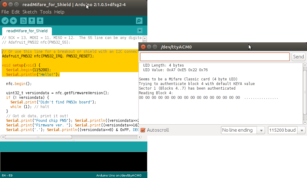
I opened the readMiFare example in the IDE, and given that I used the shield with the I2C protocol, I made the following modifications in the code, as indicated by the starting guide:
Commented out the line:
// Adafruit_PN532 nfc(PN532_SCK, PN532_MISO, PN532_MOSI, PN532_SS);
Uncommented the line:
Adafruit_PN532 nfc(PN532_IRQ, PN532_RESET);
I then saved the modified program with a new name: "readMiFare_for_Shield." I then used the USB cable to connect the Arduino board to a Linux laptop (Windows or Mac could be used as well).
A few seconds after connecting the cable, a new serial device appeared in the "/dev" directory under the name "/dev/ttyACM0" or "/dev/ttyACM1." At that point, I launched the Arduino IDE, and selected that serial device under the menu "Tools" -> "Serial Port." I then compiled the program with the "CTRL+R" shortcut and uploaded it to the Arduino board with the "CTRL+U" shortcut.
This specific example is going to initialize the board and then wait for RFID tags to get in the reading distance range of the antenna, at which point it will read the header information from the tag. The output can be seen by opening the serial monitor window with the shortcut "CTRL+SHIFT+M," and will look like the picture below:
Writing an RFID tag
I used the example mifareclassic_formatndef to format an RFID MiFare tag and store in it a short string that could be read by the NFC (Near Field Communication) of a cell phone or tablet. I opened the example in the Arduino IDE, commented out the line for the break out, and uncommented the line for the shield with I2C connection.
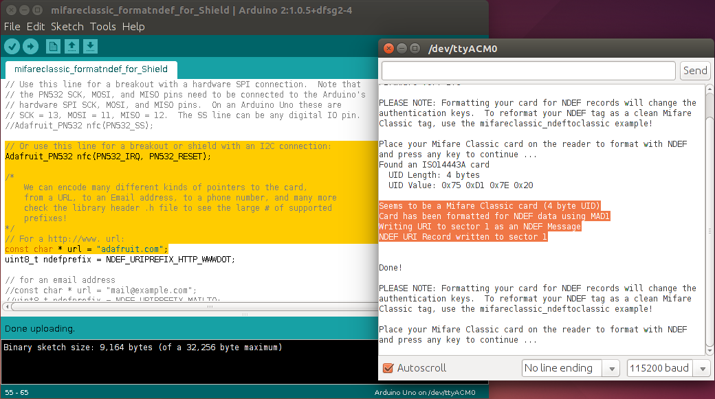
When running the example, you can see the success message in the serial monitor (right window in the figure above).
Conclusion
The Adafruit PN532 NFC/RFID controller shield for Arduino is a pretty fun component to play with. The instructions provided are very clear and detailed, but one has to pay close attention at positioning the connectors (see my rookie mistake above). After that, though, soldering is straightforward. One could also just go for wiring the five essential connectors, at the expense of ending up with a less mechanically robust setup.
Using the software examples was pretty easy and just required a couple of lines of modifications that are clearly explained in the instructions.
This is a great kit for getting familiar with RFID and NFC. And it's a must-have for educational projects and makerspaces. It's also a cool tool to have at hand for creating SWAG tags for your next community event.
Adafruit Industries provided the open hardware in this article. After the author tinkered with the hardware, we sent it back to Adafruit to make someone else happy.






2 Comments