

The inexpensive Kodak Brownie was the first camera to bring photography to the masses. The simplicity of its design meant anyone could figure out how to use it with little difficulty. Because it has essentially no controls to learn—there's just a shutter button, viewfinder, and film winder—it's even easy to use in comparison to today's cameras.
Millions of Kodak Brownies were made over the course of its 60-year lifespan beginning in 1900, and its build quality means many of them survive in good working order. A Kodak Brownie is also a good option for custom modifications—it's easily available on eBay or at tag sales, it's simple to hack, and it's cheap enough that it doesn't matter if things go wrong.
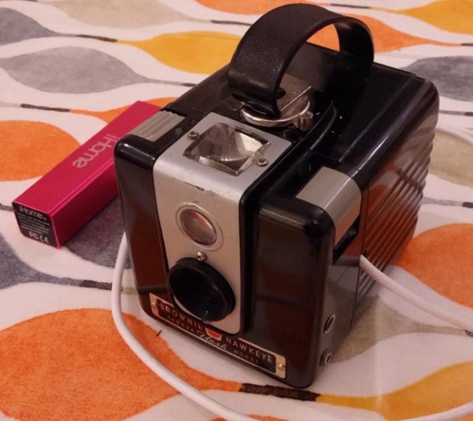
My original plan was to build a variant on the pinhole digital camera I'd previously made with a Raspberry Pi and a webcam. I had an extra Raspberry Pi Zero that needed a purpose and a Kodak Brownie Hawkeye, the variant from the 1950s with a case made out of Bakelite instead of wood or cardboard, which I'd bought for less than £5 at a local tag sale. The only key missing piece was a webcam.
[Enter our Raspberry Pi week giveaway for a chance at this arcade gaming kit.]
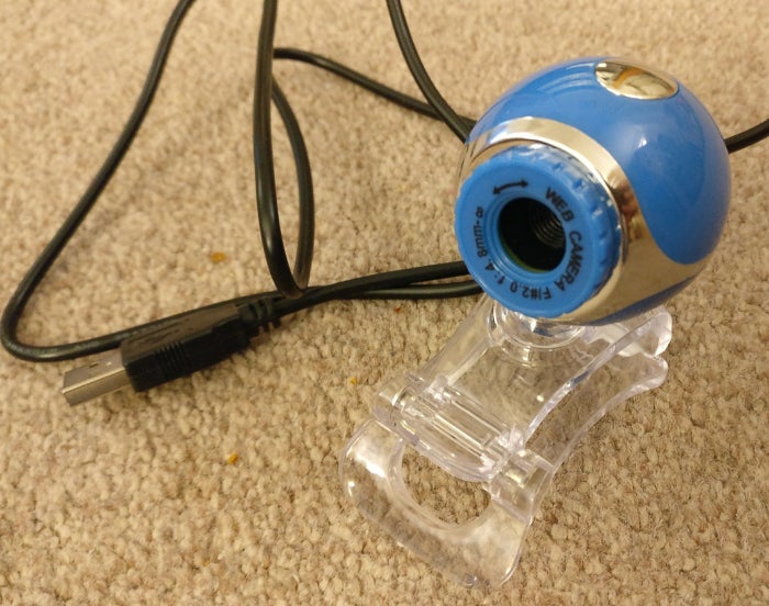
Because I'd paid less than £5 for the Raspberry Pi Zero and Kodak Brownie, I set that as my upper price limit for a webcam. Trawling eBay listings, I found a number of sellers offering a variety of 50-megapixel cameras at this price point. These technical specs were untrue—there would never be a 50MP sensor selling for that price—but it was worth a punt to discover just what the camera offered. The one I bought only provided 640×480, a mere 0.3MP with raw video only, no MJPEG, thus limiting the framerate, too. In other words, pretty awful, but only marginally more awful than expected. The plus was that it was easy to remove its case, which exposed a very compact circuit board that would be an ideal size for embedding.
opensource.com
Upon testing the webcam with an improvised pinhole plate, it was clear that the sensor had unacceptably poor low-light performance. While it could serve as a pinhole camera, it would only be usable outside in bright conditions. I wanted to build a camera that was more versatile, so I changed my plan in order to build a "normal" digital camera instead of a pinhole digital camera.
With the key parts in hand, I began design and assembly. My initial idea was to keep the Brownie's original lens in place and position the bare webcam sensor behind it. To achieve sharp focus, the sensor would have to be seated in the same position, relative to the lens, that film would be. However, Brownie film negatives were 60x60mm each, while the webcam sensor is less than 5x5mm. Testing confirmed that the webcam would have an incredibly narrow field of view, making it nearly impossible to compose shots with the crude viewfinder mirror.
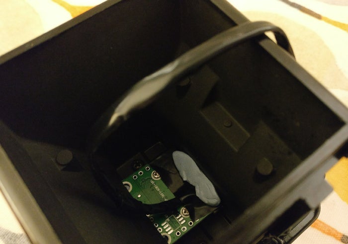
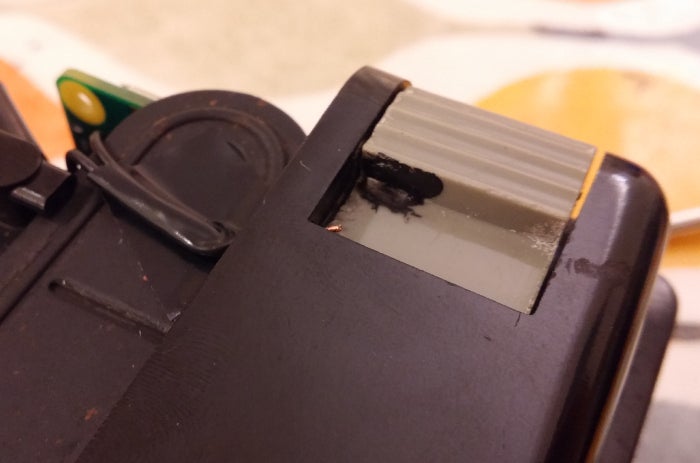
The alternative was to disassemble the Brownie and remove its plastic lens. Then the webcam circuit board could be positioned so its lens is right behind the shutter. The circuit board is just a few millimeters too large to fit into the right position, so I used a Dremel tool to carve a slot inside the case so the circuit board could slip into place.
opensource.com
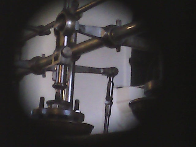
This gave the webcam a field of view similar to the original Brownie's. In fact, the field of view was wide enough that it covered the entire shutter aperture, so the resulting images had a circular vignette.
opensource.com
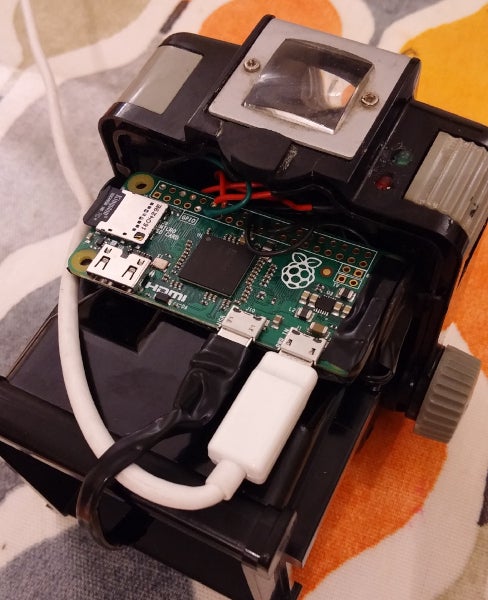
The second task was deciding how to position to Raspberry Pi Zero in the case. As luck would have it, the width of the Pi Zero is exactly the same as the length of the 620 film spool used by the Kodak Brownie, so the camera's film holders could grip the Pi Zero circuit board.
Like my previous pinhole webcam, this project uses two LEDs as status indicators: one illuminates when the power is on, and the other illuminates when the webcam is capturing an image. I drilled two small holes in the top of the Brownie case next to the shutter button; the LEDs poke through those holes, and a spot of instant glue holds them in the correct position.
opensource.com
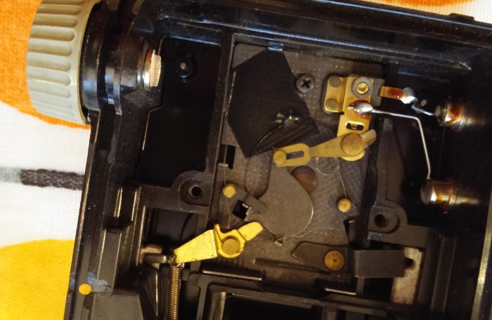
One of my key design goals was for the Kodak Brownie's shutter button to trigger image capture on the webcam. Ideally, a single press of the shutter button would capture a single image. To achieve this, I needed to create an interface between the mechanical shutter button and the Raspberry Pi's GPIO pins. After thinking about this tricky problem for a while, I conceived of a solution involving a pair of bare wires and some conductive paint. One wire connects to a programmable GPIO pin configured as an input in pull-up mode. The second wire connects to a GPIO ground pin. To implement the solution, I drilled a hole through the case, immediately below the shutter button, through which the wires pass. I stripped the insulation off the wires and glued them in position below the shutter button. Finally, I applied a blob of conductive paint to the underside of the shutter button. When the shutter button is pressed, the conductive paint shorts out the two wires and pulls the GPIO pin to ground. This change is detected by the Pi Zero and triggers the shutter.
opensource.com
The Brownie shutter mechanism is designed for film with a fixed shutter speed. It was not practical to synchronize image capture with the precise fraction of a second that the shutter was open. Fortunately, the Brownie has a long-exposure mode, where the shutter remains open for as long as the shutter button is pressed. Normally this long-exposure mode is activated by raising a second button on the Brownie, but this is somewhat tedious. With a little bit of electrical tape applied to the shutter mechanism, I hooked it permanently into the long-exposure mode.
opensource.com
Testing the shutter mechanism revealed a small problem: The webcam takes a second or two to automatically measure and adjust exposure to suit the lighting conditions. As a result, if an image were captured immediately after pressing the shutter button, it would often be underexposed. This prompted another slight design change. Rather than capturing a single image immediately as the shutter is pressed, I programmed the software to wait a second after a shutter press, then capture images continuously, one per second, until the shutter is released. In other words, it acts as a time-lapse capture device.
The only remaining task was power. The Pi Zero and webcam combination has very low power requirements, at most 200 milliamps, and a USB Lithium-ion powerpack provides an excellent, long-lasting power source. The problem is that physical size is not a hugely important factor for most powerpacks on sale today, and I haven't found one small enough to fit inside the Brownie case—it would need to be less than 6cm to stand a chance of fitting once the USB cable is plugged in, and 5cm would be even better. Also, if the battery were inside the case, there would need to be a physical power switch between the Pi Zero and the battery, otherwise you would have to open the camera to turn it on/off every time. My simple solution was to drill a hole in the case for the USB cable and leave the battery on the outside.
opensource.com
With hardware construction complete, I turned my attention to the software to control it. Rather than starting from scratch, I extended the code I wrote for the pinhole webcam Arcturus. Since my cheap webcam doesn't provide MJPEG capture, I pulled in libjpeg, a C library for JPEG image read/write, to encode the raw frames into JPEG still image files. Capturing images in raw format means the USB device must transfer large quantities of data. While this wasn't a problem on the laptop I used for development, the Raspberry Pi continually got dropped or incomplete frames from the webcam.
After countless hours debugging, I discovered the problem was with the driver for the USB controller in Linux mainline used by Pignus (the Fedora fork for the Raspberry Pi ARM6 boards). The Raspbian kernel, by comparison, has an out-of-tree driver for the USB controller, which turned out to work fine. The other software change I made was the one I mentioned above to continuously capture still images.
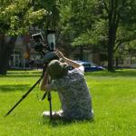
Here is the first video I took with my custom-built Kodak Brownie digital time-lapse camera, of a steam engine running at Kew Bridge in London.
This was originally published on Red Hat software engineer Daniel Berrangé's blog f/138 and is reprinted with permission.


Comments are closed.