A while ago, I created a small extension board for the Raspberry Pi to do some hardware hacking.
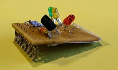
The first iteration was on a bread board with some wiring to connect to the Pi. For the next iteration, I took a stripe PCB and soldered the components onto it. It worked, but it wasn't pretty:

As I worked on the concept, I decided I needed some printed circuits (PCB). The main motivation here was to be able to run some workshops at the local Java User Group, where people would solder the board and then program it.
I played around with some options for producing the layouts. Unfortunately, nothing was really great for hobbyists like me. On top of that, I also did not want to manufacture the PCBs myself with all the chemicals needed. After some more searching I found Fritzing, which was exactly what I was looking for.
Fritzing is an open source application that allows users to create schematics by selecting parts from a large part library, connecting them, and laying them out on a virtual breadboard.
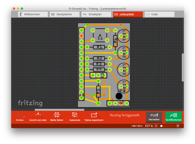
After the schematic is created, Fritzing can autoroute the schematic onto a PCB design (it supports single and double-sided PCBs). Most of the time, though, it needs some human help.

Once you're happy with the designs and/or the PCBs, you can export them as images (which is what you often see in the Arduino documentation). Or you can send them to the Fritzing Fab service.
Fritzing was created by FH Potsdam in Germany and is now evolving via the Friends of Fritzing Foundation. Project sources are available on GitHub.
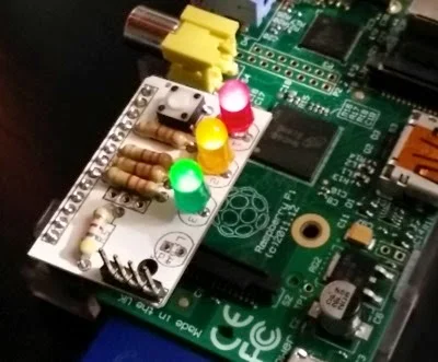
I went the route of the Fab service, waited a bit, and got some very professional PCBs back. The following image shows the final PCB assembled and mounted on a Pi.

The other nice thing about Fritzing is that it allows you to publish your designs so that other makers can take them, create them, or remix them to their needs. The above board can e.g. be found here.
When you put the board onto the extension header of the Pi (the inner row closest to the CPU), the following little shell script will light all LEDs and then display the current temperature every second
 #!/bin/sh
 set -x
 cd /sys/class/gpio
 for i in 10 22 27
 do
 echo $i > export
 sleep 5
 echo out > gpio$i/direction
 sleep 5
 echo 1 > gpio$i/value
 done
 cd /sys/bus/w1/devices/10-*
 while true
 do
 cat w1_slave | grep t=
 sleep 60
 done
There is one line that may need tailoring, depending on the variant of DS1820 thermometer chip you have:
cd /sys/bus/w1/devices/10-*
One thing where I'm not yet sure about is whether the DS1820 actually needs the phantom power. In an older experiment with the chip, I did not connect pin 3 at all. I think this additional power may even heat the thermometer chip, as the values that I currently get are some 5-6 degrees too high.
To read the state of the push button you can use this script:
 cd /sys/class/gpio
 echo 9 > export
 cd gpio9
 while true ; do cat value; done
This article was originally posted on the blog, Some things to remember.
Hardware
A collection of articles on the current state and future of open hardware.


4 Comments